 简体中文
简体中文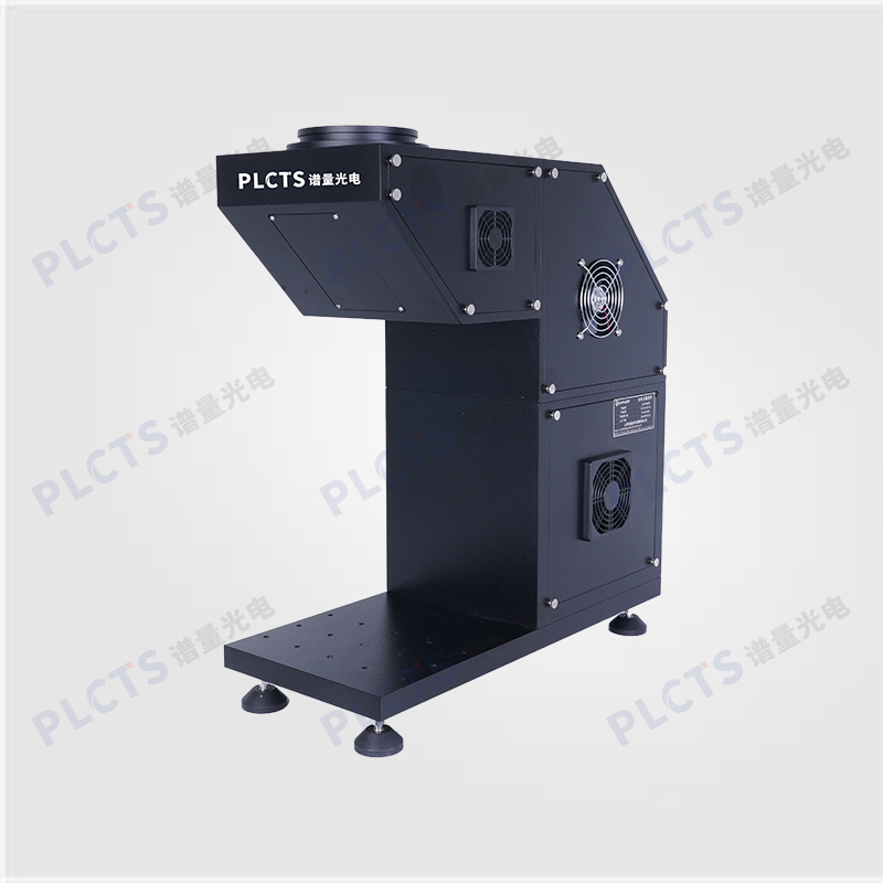
扫一扫
关注公众号
PL Optics Class AAA Steady-State Solar Simulator features a high-pressure xenon lamp with coaxial collimation optics, adjustable irradiance (0.7–1.2 Sun), Class A spectral match, uniformity & stability, and spot sizes from 5050 mm to 200200 mm for photovoltaic device testing.
Steady-State Solar Simulator delivers continuous, stable sunlight–like illumination, making it ideal for photovoltaic and photoelectric device testing. It’s especially suited for slow-response cells such as thin-film and dye-sensitized solar cells.
Our Class AAA Steady-State Solar Simulator uses a high-pressure xenon lamp and coaxial collimation optics to achieve high irradiance and excellent uniformity, ensuring reliable performance for all solar‐cell and photoelectric characterization.
Simple Optical Design with high electro-optical conversion efficiency
Adjustable Xenon Lamp Power via a unique power-supply circuit
Separable Power Unit & Lamp Housing for enhanced portability
Secondary-Filter Optical Head for superior filtering performance
Advanced Heat-Dissipation Housing extends lamp life with optimal thermal management
Imported Xenon Bulb delivers focused high-density output, boosting experimental throughput
Modular Construction ensures maximum safety and stability, enabling 24/7 continuous operation (attended)
Our NPLS Series solar simulators comply with both IEC international and national standards, and can be verified using the following standard methods:
1、Irradiance Uniformity:Measure the short-circuit current of a reference PV cell at multiple points across the illuminated area.
Non-uniformity (%) = (Max – Min) / (Max + Min) × 100 (±)
2、Irradiance Stability:Place the same reference PV cell under continuous illumination for 1 hour. Record the current over time.
Instability (%) = (Max – Min) / (Max + Min) × 100 (±)
3、Spectral Match:Use a calibrated spectroradiometer to measure the output spectrum and compare against the AM 1.5G reference curve.
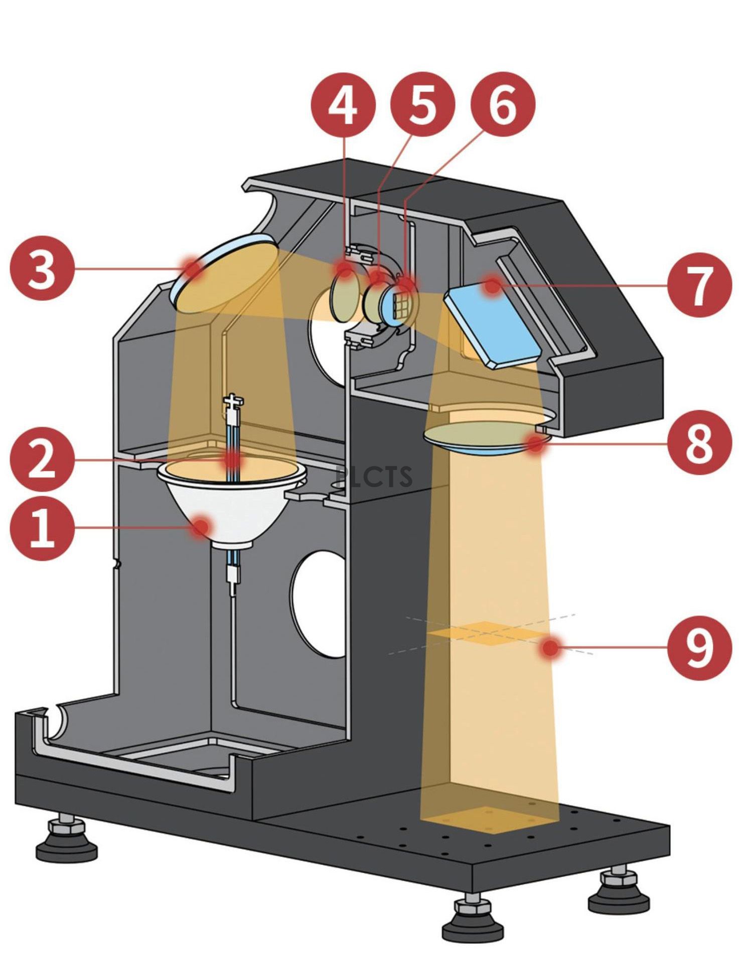
1 Ellipsoidal Reflector
2 Xenon Lamp Bulb
3 Metallic Folding Mirror
4 AM 1.5G Solar Filter
5 Optical Integrator Field Lens
6 Optical Integrator Projection Lens
7 Glass Fold Mirror
8 Collimating Lens
9 Work Surface
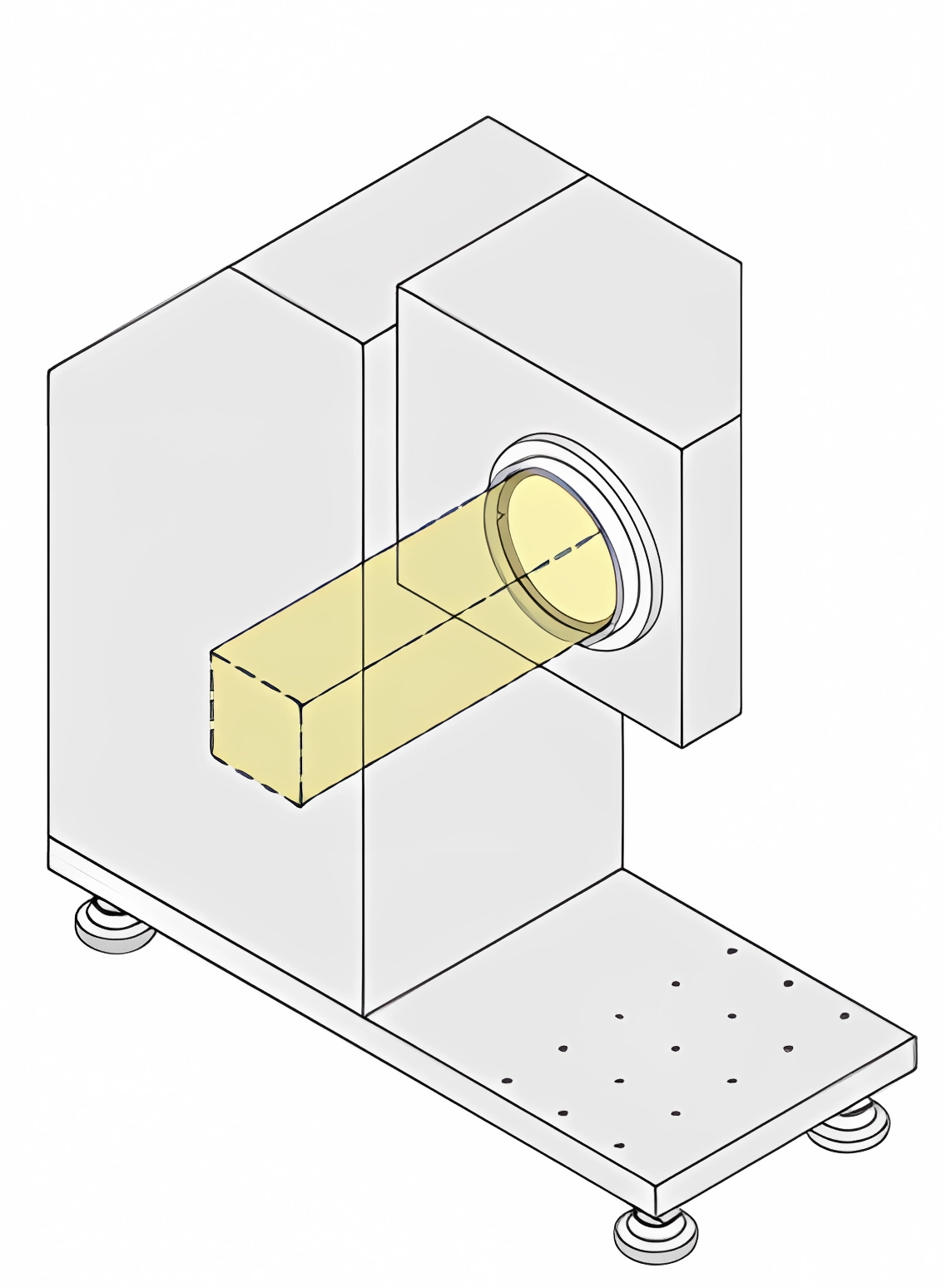
The NPLS-W Series Class AAA steady-state solar simulator can be configured for three emission directions
● Downward Emission (Standard): Sample is placed directly underneath the simulator for testing.
● Upward Emission: Simulator mounted below a glove box, illuminating the sample through the access port.
● Side Emission: Choose lateral output to suit your sample’s mounting orientation.
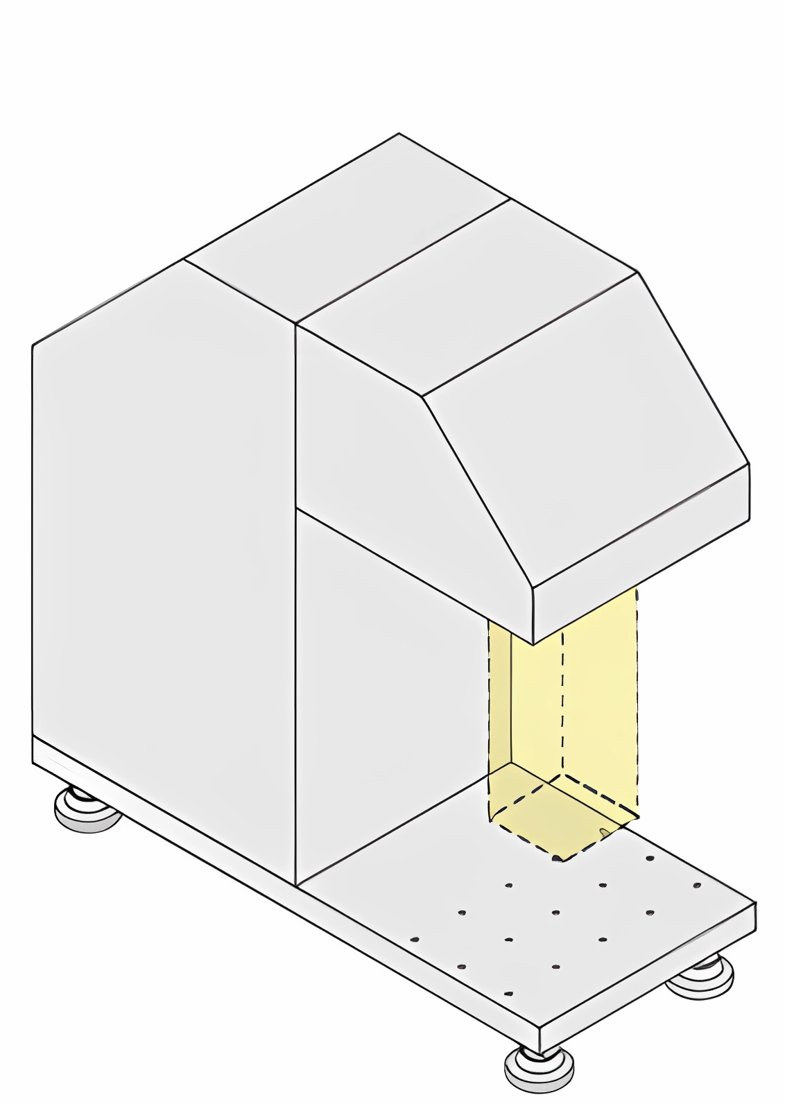
↑Standard Downward Emission
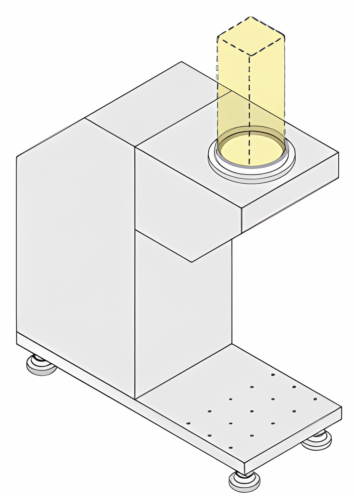
↑Upward Emission
↑Side Emission