 简体中文
简体中文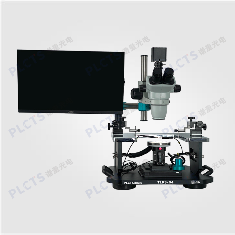
扫一扫
关注公众号
The PL Optics TLRS Simplified Probe Station is a compact, cost-effective solution for high-throughput electrical parameter testing of semiconductor chips on industrial production lines.
The probe station, also known as the probe test station, is primarily used to provide a testing platform for the electrical parameter testing of semiconductor chips. It can accommodate chips of various specifications and offers multiple adjustable test probes and probe holders. When paired with measuring instruments, it can perform parameter testing such as voltage, current, resistance, and capacitance-voltage characteristic curves for integrated circuits. It is suitable for research experiments and analysis of materials, chips, and other components, as well as for random testing.
The TLRS Series Entry-Level Basic Probe Station is a compact, cost-effective platform specifically designed by our company to meet the needs of industrial users for production testing. While maintaining a low-cost advantage, it supports fundamental electrical measurements on production lines, making it an ideal choice for high-throughput testing in industrial applications.
● Compact structure, practical functionality, and excellent cost performance
● XYZR four-axis sample stage with 10 μm resolution; 360° rotation with locking
● Compatible with electrodes/PADs larger than 1 μm
● Compatible with various microscope systems; supports optical path input for optoelectronic mapping measurements
● Leakage current measurement accuracy up to 10 pA / 100 fA (within shielded enclosure)
● Precision transmission mechanism for linear motion without backlash
● U-shaped probe arm accommodates multiple probe holders
● Compact and portable design with honeycomb vibration isolation base for improved testing stability
Optical Isolation Platform (table surface > 600mm * 600mm), One computer (with standard VGA and USB interfaces), Keithley 2400 Digital SourceMeter (including software), etc.
During testing, connect the probe station and digital source meter. The probes are connected to the object under test. Use a microscope to observe and confirm that the two probes are in contact with the surface of the object under test. Once the connection is established, open the source meter software, select the appropriate parameters, and the I-V characteristic curve for the contact point can be obtained.