Detailed Guide to Integrating Spheres (Structure · Principles · Applications)
发布时间:2025-09-01 11:54:26人气:
What is an integrating sphere?
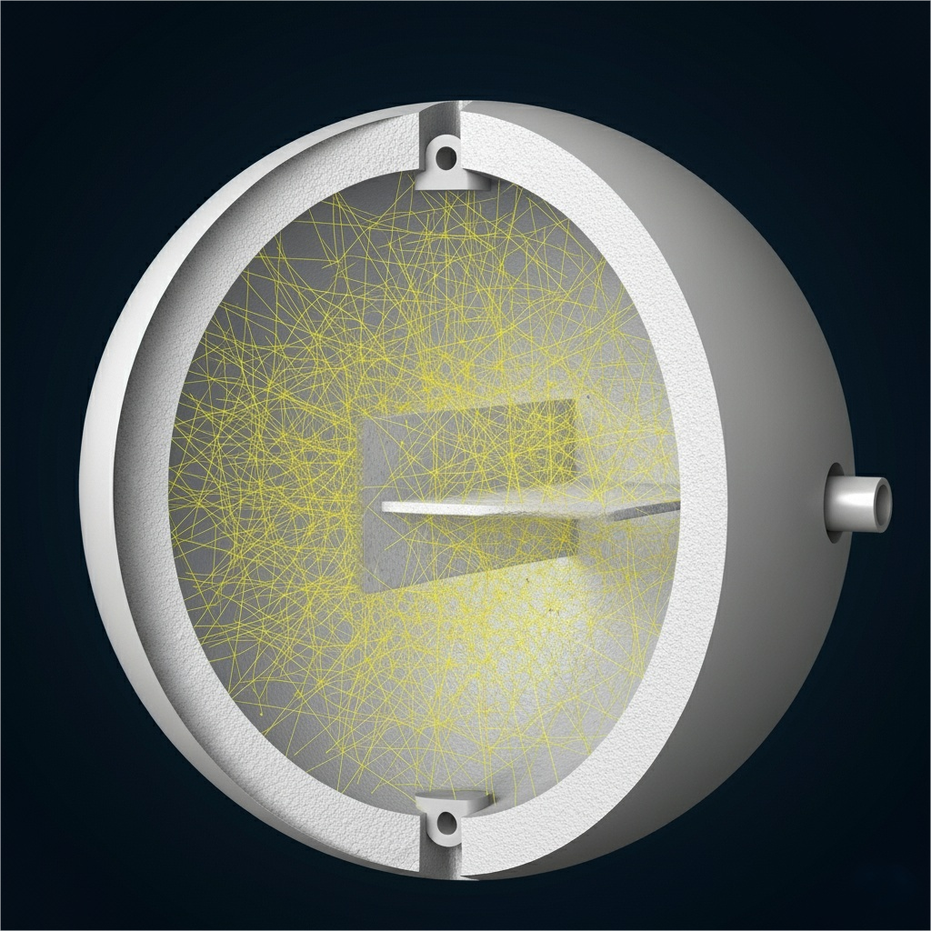
An integrating sphere is a hollow cavity—typically spherical—with a highly reflective, diffuse inner coating. Light entering the cavity undergoes many reflections. Directional information is lost, leaving a spatially uniform, quasi-isotropic radiation field. A detector coupled to the sphere therefore measures signals that reflect the total flux or power, largely independent of the original beam’s position or angle.
Structure
Shell: rigid metal or polymer housing, usually matte black outside to minimize ambient stray light.
Inner wall: diffuse high-reflectance coating or lining (e.g., PTFE, BaSO₄, Spectralon) providing 95–99% reflectance over broad bands (commonly 200–2500 nm).
Geometry: a true sphere is standard, though ellipsoids or hybrid forms exist—uniform diffuse reflection is the key.
Ports: input, output, and sample ports are machined into the wall for coupling sources, detectors, and samples.
High wall reflectance ensures rapid “mixing” of rays and a uniform internal field with minimal losses.
How it works
Light enters through an input port and strikes the diffuse wall.
After dozens of reflections, directional memory is erased.
The cavity field becomes uniform and nearly isotropic.
A detector views the integrated field, which depends mainly on total radiant flux—not on beam position or angle.
This uniformity enables robust measurements of total flux, power, reflectance, and transmittance.
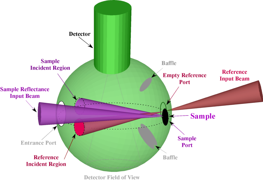
Ports & interfaces
Input port: couples a light source or fiber (often SMA905 or FC/PC).
Output port: routes uniformized light to a detector or spectrometer.
Sample port: mounts thin films, powders, solids, or cuvettes for transmission/reflectance tests.
Detector interface: sometimes the detector mounts directly on the sphere to avoid relay losses.
Auxiliary/monitor ports: for reference photodiodes or auxiliary sources.
Design tip: total open-area should generally be kept under ~5% of the interior surface. Larger openings boost coupling but degrade uniformity.
Applications (with common configurations)
1) Total luminous/radiant flux (2π / 4π configurations)
4π mode: source at the sphere center for full-space (4π) flux.
2π mode: source mounted at a port for hemisphere (2π) flux—useful for luminaires.
Baffles: block direct view between source and detector to reduce bias.
Port geometry: typical 0°/90°/180° layouts avoid ports facing each other.
Fluorescence QE: excite a centered sample; collect omnidirectional emission; separate excitation/emission bands.
IR linings: gold/aluminum for ~2–20 µm (and beyond, as required).
Mini spheres: diameters < 50 mm for portable, quick fiber coupling to micro-sources.
At-a-glance comparison
Use case
Key geometry
Typical ports & features
Notes
Total flux (2π/4π)
Center source (4π) or port-mounted (2π)
Baffles; monitor PD
4π for bare sources; 2π for luminaires
Spectral measurements
Fiber output to spectrometer
SMA905/FC; sample insert
Track relative drift with PD
Reflectance / Transmittance
8/d or d/8 incidence
Specular trap (SCI/SCE)
Coatings/films characterization
Laser homogenization
Small input, large uniform output
Baffles; thermal management
Consider diffusers/ND wheels
Imaging calibration
Large exit matching FOV
Built-in stabilized sources
Radiance stability via feedback
Fluorescence QE & IR
Centered excitation; IR linings
Band separation optics
Mini spheres for portability
Practical design notes
Coating choice: PTFE liners offer broad UV–NIR performance; BaSO₄ is economical for VIS–NIR; gold/aluminum help in the thermal IR.
Port budgeting: keep total open area small (< ~5%) to preserve uniformity; add baffles to block direct lines of sight as needed.
Detector placement: placing sensors on the sphere reduces relay losses; otherwise, use short, low-loss optics/fibers.
Thermal limits: for high-power laser work, incorporate cooling and temperature monitoring to protect coatings.
FAQ
Why do integrating spheres “ignore” beam angle and position?
Because the inner wall is highly reflective and diffuse, light is randomized over tens of reflections. The detector then “sees” the integrated field dominated by total flux.
What’s the difference between SCI and SCE?
SCI (specular component included) counts mirror-like reflections; SCE (specular component excluded) traps them out. Coatings and glossy samples are often characterized in both modes.
2π vs 4π flux modes?
4π: source at the center measures all directions. 2π: source at a port measures the hemisphere—useful for fixtures or luminaires that naturally emit into half-space.

 简体中文
简体中文